
Visualize all those mysterious electronic signals with an oscilloscope!
Learn how to build and use a super simple $30 oscilloscope perfect for electronics hobbyist applications. It’s also a great way to get started using some of the fancier oscilloscopes!
Reading and Changing the Oscilloscope Display
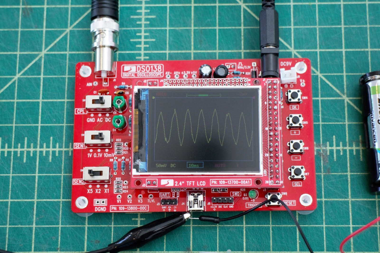
Every oscilloscope has a window that displays the voltage output of your signal. On every display, the y-axis is voltage, and the x-axis is time.
 You can zoom in and out of the display grid by adjusting the “Volts per division”* or “Seconds per division”.
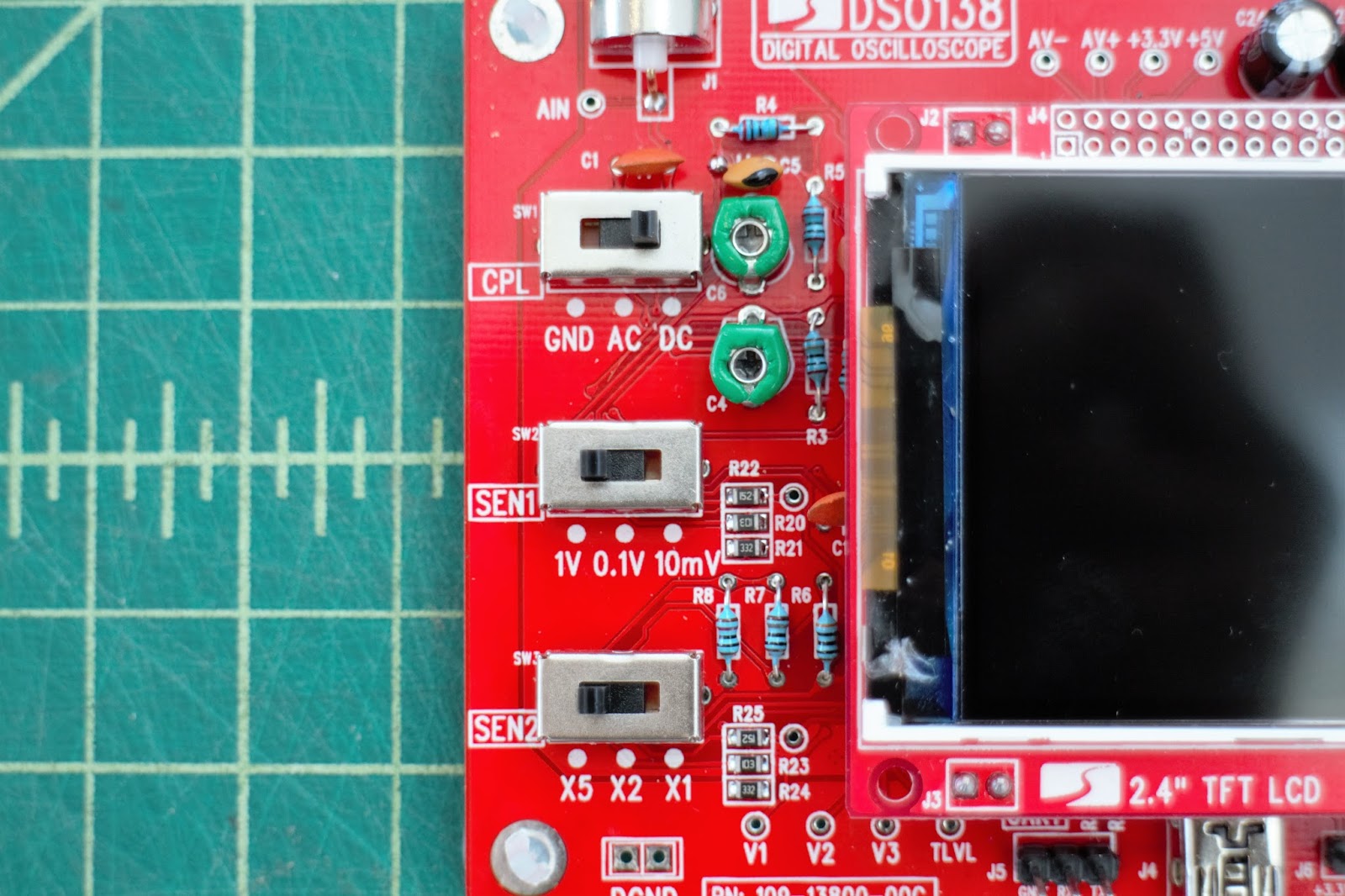
On this oscilloscope, the voltage adjustment switches are on the left side (bottom two switches), and they let you zoom out to as much as 5 Volts (“V”) per division, and zoom in to 10 mV per division.
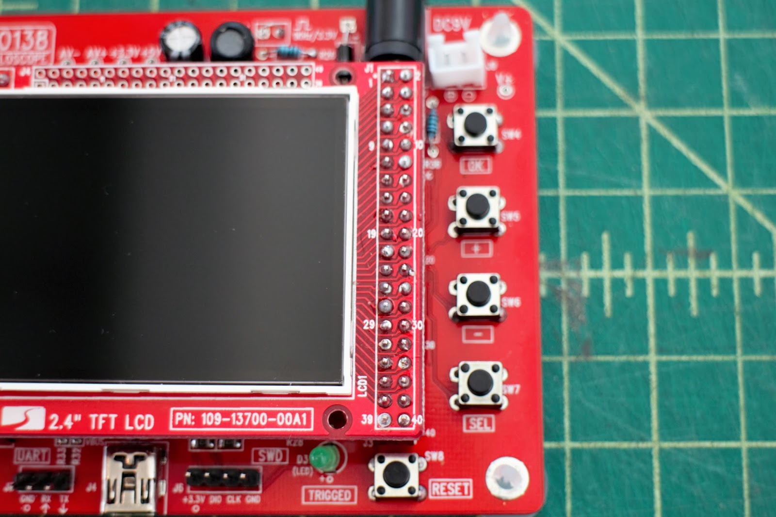
Adjust the time scale using the “+” and “-” buttons on the right side.**
*”Per division” means the size of the squares, e.g. 1V per division means that each square is 1V in height, 1 second per division means that each square is 1 second wide.
** Be sure that the time scale is selected (will be highlighted with a box around it — this is the default selected setting, change settings using the “sel” button, described in more detail in the next section.
Other Basic Features

This oscilloscope has all the expected features of larger, more expensive ‘scopes, and also is a great introduction to some of the more complex versions.
On the left side, the top switch allows you to choose between a ground signal, a DC signal, and an AC signal. On the right side of the oscilloscope are four buttons:
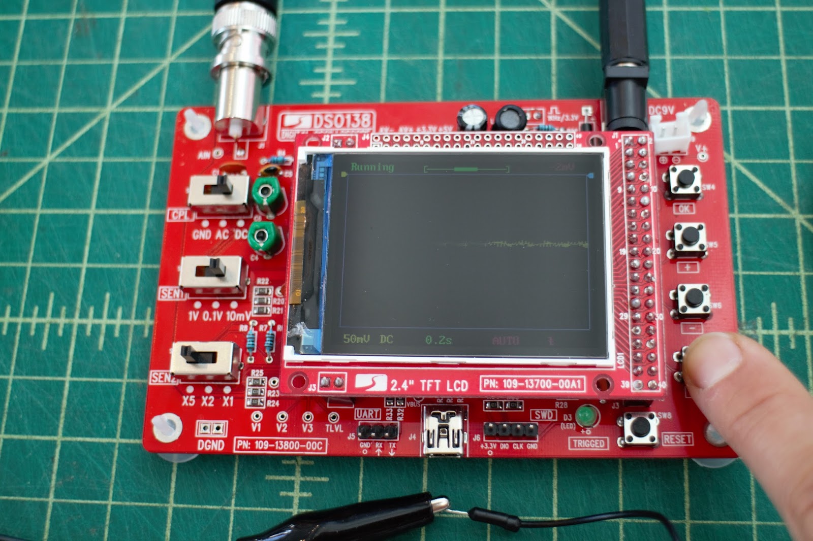 1. The “ok” button (very top button): Pushing it once takes a snapshot of the screen, which can be saved to the oscilloscope. Holding this button down displays key numeric values about your signal, like the maximum and minimum voltage, signal frequency, etc.
2. The “+” button: Similar to an up arrow key, pushing this button allows you to sort through options.
3. The “-” button: Same as the + button, but, you know, scrolls down
4. The “Sel” button: Pushing this button allows you to select different features (described in order):
A. Change the time scale.
B. Set how the oscilloscope display refreshes – “Auto”, “Norm,” or “Sing”. More on these in the next section.
C. Set the trigger slope. More on this in the next section.
D. Change the trigger level. More on this in the next section.
E. Adjust the horizontal position of the oscilloscope display.
F. Change the vertical position of the display.
Oscilloscope Trigger
Oscilloscope triggers cause the oscilloscope to display a signal. Triggers are set at a specific value, or “trigger level,” along a specified direction, or “trigger slope” (more info below).
The trigger helps to display the exact electrical signal that you want, so that you get a stable display and measurement. In this ‘scope, the trigger is set on the right side of the display and the LED at the bottom flashes when the trigger is detected.
The simple oscilloscope in this tutorial has three trigger modes that you can switch between using the “+” and “-” buttons:
- Automatic (“Auto”): Display continually refreshes, regardless if triggers are met.
- Normal (“Norm”): Display only refreshes if the trigger is met.
- Single (“Sing”): Same as normal mode, waveform display is held after a trigger has been detected.
More on Trigger Level and Trigger Slope!
The Trigger Level is a set, internal voltage that is compared to the signal, or input, voltage. The oscilloscope triggers when the signal voltage is equal to the trigger voltage. If an electronic signal rises and falls, then the trigger would happen twice: once when the signal is rising and again when the signal is falling. The trigger slope lets you choose which voltage (rising or falling) to trigger on.
Connecting a Component!

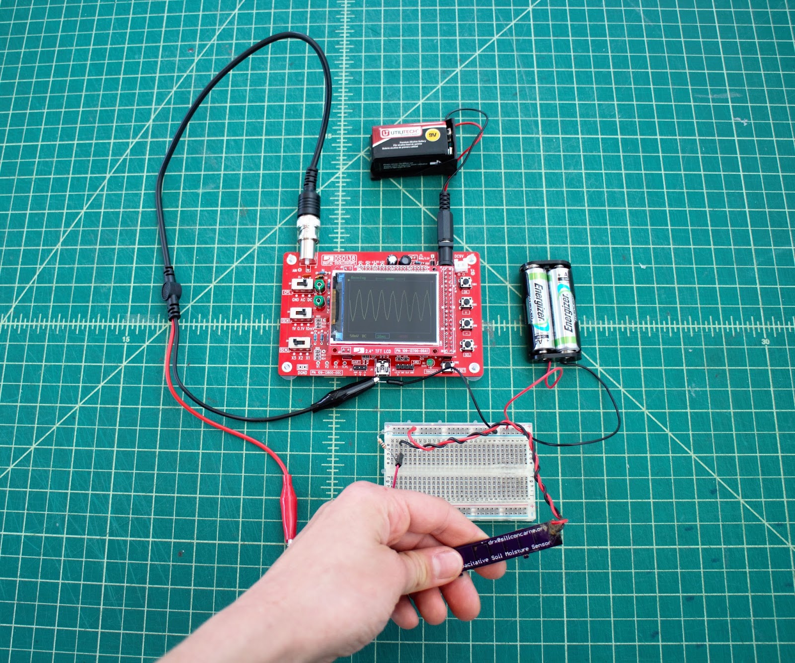
Now, to see the electrical signals at work in the world around you, connect the black lead to ground, and the red lead to the part of the circuit that you want to measure the voltage.

For example, if you want to measure the voltage output of a sensor, like the capacitor in the photo to the right, you want to connect the red probe after the sensor.
You may also want to calibrate your scope using the on-board signal. See the datasheet for more info.
Finally! Turning on the DSO138 Oscilloscope

The an oscilloscope kit in this tutorial takes about 2 -3 hours to assemble (instructions here), but is definitely worth it because many reasons! Here are a few: It’s a great way to learn circuit components, get familiar with schematics, and practice soldering (and de-soldering….). And, honestly, it’s pretty relaxing.
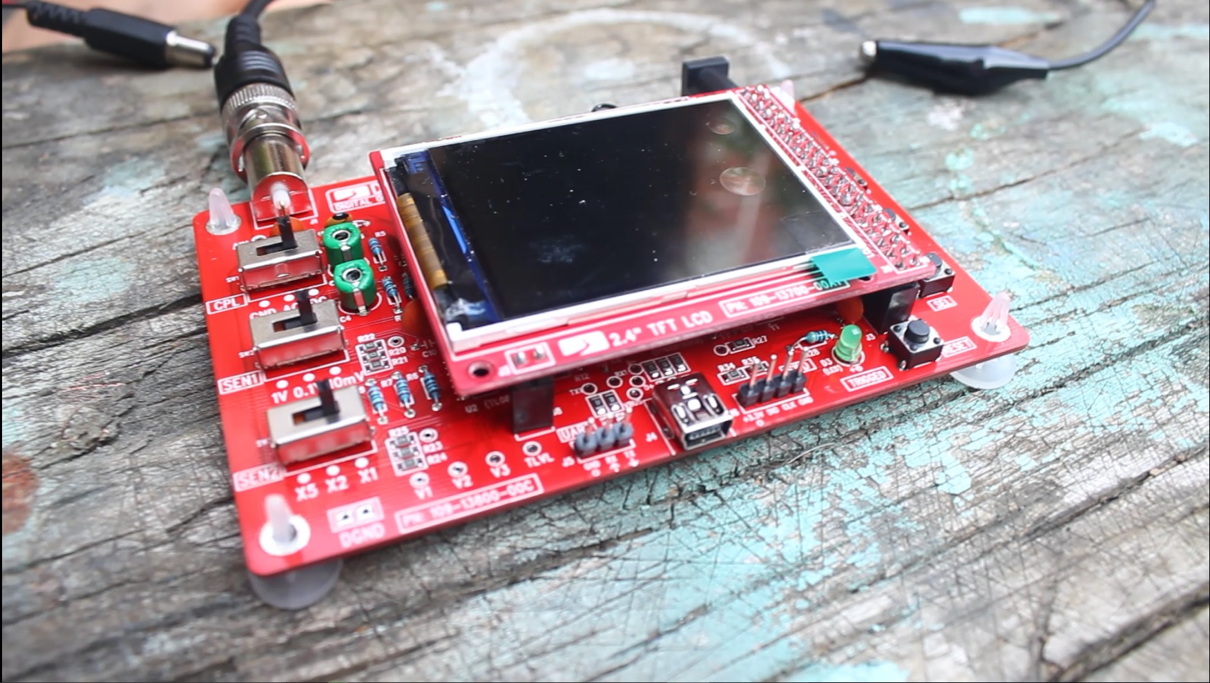
Once you’ve got the ‘scope assembled, it needs 9V and about 0.1A. There are two power ports: a barrel jack and a male JST connector. You can use a 9V battery with the barrel jack (OMG it’s portable!), or a power supply with the JST connector.
The exposed wire on the top of the oscilloscope is a square wave signal to help you calibrate the signal (see the datasheet for more info).
Be sure to use less than 12V or you risk heating up the board and possibly damaging it (don’t let the black smoke out!).
Plug and Play!
Now you know all the basics to connect your oscilloscope to sensors, your tongue, and other low power sources to watch the wonderful world of electricity at work!
Please leave a comment in the tutorial if you have any questions or would like more info about the oscilloscope kit. Now go forth and explore all that electricity! 😀
Interested in building a capacitive touch sensor like the one used in this tutorial? Check out this tutorial!