The motivation for this project was to create a controller that allows users to “play” light like it is an instrument with gesture control, custom visuals, and brightness/speed dials.
Considering how pricey consumer light controllers can be (often $100 bucks or more- not including the lights!) we decided to make a cheaper, more customizable solution! One aspect of this project that we were particularly excited about was the low barrier to entry. Most users pick up the controller in 2-3 songs, unlike other light toys (gloving, poi, ect) that require a much larger practice investment.
Here is our approach, you are welcome to use as-is or modify the project for all of your wild and wonderful needs!
Build Time: 2-3 hours
Estimated Cost: $80 of materials
Project Materials
| Case/Mounting Board (I used a wood box from a craft store) | ||
| Seeed Grove Sound Sensor v1.6 (Optional- Not used in this version) | ||
| Addressable LED Strips (2-3) | ||
| Rotary Potentiometer (2) | ||
| Digilent Pmod KYPD | ||
| Ultrasonic Rangefinder | ||
| Arduino UNO |
Project Tools
| Dremel | ||
| Soldering Iron | ||
| Hot glue gun |
Build Overview
Design Considerations
One of the challenges with a project like this is the number of buttons it needs. Even in my more conservative designs, I wanted to have around 8 buttons to manage the different visual sequences, color palettes, and other mode selection. Wiring up that many buttons can be tedious and adds more points of failure. Additionally, the Arduino Uno board has a limited number of digital inputs. Luckily, the Pmod KYPD solves both of these issues!
The Pmod KYPD’s small form-factor allows it to fit neatly onto any baseboard without taking up too much space. I am using a free wood sample I got from my local hardware store as my mounting panel.
Electrical Schematic
Build Process
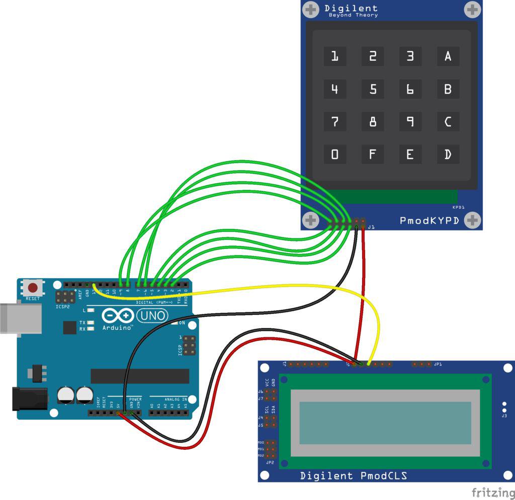
1. Start by connecting the Pmod KYPD to the Arduino Uno digital pins as shown in the above Fritzing diagram.
2. Next, wire in your potentiometers to Analog Pins A5 (brightness) and A4 (speed).
3. Attach the LED Strips to Ground and 5V, then wire both signal pins into Digital Pin 11.
4. Wire up the sound sensor to power and ground, and the white wire to A1 and yellow wire to A0.
If you do not have the connecting cable as a reference, the yellow wire is the outside one, and more documentation on the sensor is here. For the Ping sensor/Ultrasonic rangefinder Trig is on Digital Pin 13 and Echo is on Digital Pin 12 (in addition to power and ground of course).
5. The PmodBTN is wired to Analog Pin 0-4, along with ground and power.
Code
1. Download the 2.0_Code.
2. Activate the FastLED and Keypad library (both found in the Arduino IDE library manager).
Keypad is not listed first when you search for it, you will have to scroll down until you find the one by Mark Stanley and Alexander Brevig.
3. Copy and paste the code into the Arduino IDE and click upload. Now it is time to play around with the board!
Note: Buttons 3 and 4 are attached to the ping sensor so try putting your hand over the sensor when you activate those visualizers.
Read through the code and our comments to see where you can make changes or add in new features. Have fun and feel free to expand this project to add more visualizers, sensors, ect!
More information
We updated the code and added more functionality, download LEDController_2 if you want the additional features. This code also requires the FastLED and KeypadUpload libraries.
In the new code the visualizers are:
- Flow
- Waterfall
- DoubleBounce
- Hand Bounce
- Levels
- Center Levels
- Blob
- AmbientSpots
- Segments
- Pulse
The numbers correspond to the visualizers and the letter to color palettes.
For the PmodBTN module, the effects are the following:
- Top Right: Strobe
- Bottom Right: Bounce Out (Double Bounce Single Sequence)
- Bottom Left: Pause
- Top Left: Not Set
Effects are temporary animation sequences that interrupt the current visualizer. They perform a single loop, then the current animation resumes. The one exception is the pause button, which requires you to unpause or skip out of it using a different effect.
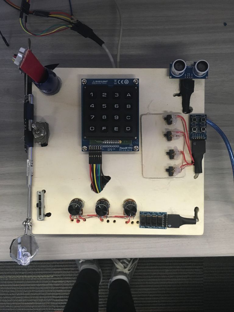
Mechanical Design:
For our final version, we took a hollow wooden box from a local craft store and placed/traced out each component on the box. Then we dremeled a hole under the spot for the wires and set the Arduino inside the box. Finally, we mounted each piece with hot glue (after running the wires) and clipped the box shut with the metal clasp that came on it.
That’s it! Please let us know if you have any questions or issues and definitely share your creations with us!
Happy making!