
Bring science fiction to life with a personalized light-up outfit! EL wire is a delightfully futuristic-looking luminescent wire that has the added benefit of staying cool, making it ideal for wearable projects. Combining sensors and a microcontroller with EL wire allow for a wide range of feedback and control options.
This project uses the SparkFun sound detector and the EL Sequencer to flash the EL wire to the rhythm of ambient sound, including music, clapping, and talking.
Materials
Electronics

El Wire comes in a variety of colors, so pick your favorite(s)!
- EL Sequencer
- Lithium Ion Battery
- 5V FTDI BOB (or cable)
- DC to AC Inverter – 3V
- Sound Detector
- Stackable Header pins (15 total: 5 for FTDI BOB, 5 for EL Sequencer, and 5 for sound detector)
- Five (5) Female-to-Female Breadboard Wires (or regular wire is fine, too)
- Note: Purchase **three (3) JST connectors** for the EL wire, battery, and inverter if these components do not already have connectors.
Costume

- Article(s) of clothing
For a Tron-esque look, go for stretchy black material. Yoga pants and other athletic gear work great!
- Belt
- Old jacket with large pocket, preferably zippered or otherwise sealable.
The pocket will house the electronics. If you intend to wear the costume outdoors in potentially wet weather, choose a pocket that is waterproof (i.e. cut a pocket from a waterproof jacket).
- Piece of packing foam or styrofoam (to insulate the sound detector).
Tools

- Wire Strippers
- Epoxy (waterproof)
- Scissors
- Needle + thread OR fabric adhesive
Build it! Pt. 1
CAUTION: Although it is low current, EL wire runs on high voltage AC (100 VAC). There are exposed connections on the EL Sequencer board so BE CAREFUL when handling the board. Always double (and triple) check that the power switch is OFF before touching any part of the board. For final projects, it is recommended to coat all exposed connections in epoxy, hot glue, electrical tape, or other insulating material.

1. Test EL Sequencer with EL Wire.
Connect the inverter, battery, and at least one strand of EL wire to the EL Sequencer. (Note that the two black wires of the inverter correspond to the AC side.)
Be sure that the EL Wire lights up and blinks when you power the EL Sequencer on battery mode.

2. Solder header pins onto 5V FTDI pinholes on the EL Sequencer and onto the VCC, ground, and A2 input pins.
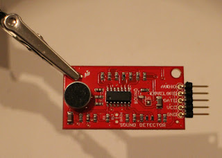
3. Solder header pins to the sound detector.
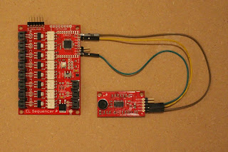 4. Connect sound detector to EL Sequencer via female-to-female breadboard wires (or solder wire onto header pins).
Connect the sound detector VCC and ground pins to the VCC and ground pins on the EL Sequencer. Connect the sound detector gate output to the A2 input pin on the EL Sequencer. If you are using the envelope and/or audio output signals, connect these to pins A3 and A4 on the EL Sequencer (more on this in the Program It! section).
Build it! Pt. 2
 1. Make a protective casing for the sound detector using packing foam or styrofoam to prevent jostling or other physical vibrations (aka collisions) from triggering it.
Place sound detector on top of foam, outline the board with a pen, and cut out a hole in the foam for the detector to fit snugly inside. Also recommended to epoxy the wires onto the foam (but not the sound detector board).

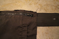
2. Cut out a pocket from the jacket and sew onto the belt.

3. Put belt on, connect EL Wire to EL Sequencer, and place EL Sequencer in pocket pouch. Determine approximate placement of each EL wire strand based on location of electronics.
Build it! Pt. 3

1. Mark and/or adhere the base of the EL wire JST connector onto clothing, allowing the full length of the connector to flex. Be sure that the JST connector can easily reach the EL Sequencer.

2. Starting at the basse of the JST connector, attach EL wire strands to your chosen article of clothing.
Sew EL wire onto clothing using strong thread or dental floss, or use an appropriate fabric adhesive.
Prior to adhering the EL wire, it is recommended to use safety pins to determine placement of the EL wire on each article of clothing while you are wearing it. EL wire is flexible but not so stretchy, so give yourself some wiggle room.
It is also recommended to use separate EL wire strands on different articles of clothing to facilitate the process of taking it on/off.

Program it!
1. Connect EL Sequencer to computer via 5V FTDI BOB or cable.
2. Program the EL Sequencer using the Arduino platform; the EL Sequencer runs an ATmega 328p at 8 MHz and 3.3V.
3. Determine how you want to use the sound detector output(s) to control the EL wire. The sample program below utilizes the gate channel output to turn on the EL wire if there is a sound detected.
Sample Program:
// Sound Activated EL Wire Costume<br>// Blink EL Wire to music and other ambient sound.
//JenFoxBot
void setup() {
  Serial.begin(9600);
  // The EL channels are on pins 2 through 9
  // Initialize the pins as outputs
  pinMode(2, OUTPUT);  // channel A
  pinMode(3, OUTPUT);  // channel B
  pinMode(4, OUTPUT);  // channel C
  pinMode(5, OUTPUT);  // channel D
  pinMode(6, OUTPUT);  // channel E
  pinMode(7, OUTPUT);  // channel F
  pinMode(8, OUTPUT);  // channel G
  pinMode(9, OUTPUT);  // channel H
//Initialize input pins on EL Sequencer
  pinMode(A2, INPUT);
}
void loop()
{
  int amp = digitalRead(A2);

  //If Gate output detects sound, turn EL Wire on
  if(amp == HIGH){

    digitalWrite(2, HIGH); //turn EL channel on
    digitalWrite(3, HIGH);
    digitalWrite(4, HIGH);
    delay(100);
  }

    digitalWrite(2, LOW); //turn EL channel off
    digitalWrite(3, LOW);
    digitalWrite(4, LOW);

}
This program is just one example of what is possible with the SparkFun sound detector. Depending on your needs, different responses can be achieved by using the “envelope” and “audio” outputs of the sound detector. The EL Sequencer can individually control up to 8 different EL wire strands using the three sound detector output signals, so there are tons of possiblities to customize your sound-activated outfit!
More information about the sound detector output signals:
The gate channel output is a digital signal that is high when a sound is detected and low when it is quiet. The envelope channel output traces the amplitude of the sound, and the audio output is the voltage directly from the microphone.

In the photo provided, the red trace corresponds to the gate signal output, the light green trace corresponds to the envelope signal output, and the dark green trace corresponds to the audio signal output.
Test, Secure, & Show Off!
 Connect all components to the EL Sequencer (inverter, battery, sound detector) and place in belt pouch. Turn the system on, make some noise (e.g. clapping, snapping, or music) and check that the EL wire flashes when there is a sound.
If the outfit works as expected, secure all connections by coating them in a (thin) layer of epoxy. Let dry for at least 24 hours. Epoxy is a very permanent adhesive, so if you want to reuse any of the components, try other adhesives like hot glue or electrical tape (less secure, but adjustable and removable).
You can reduce the overall strain on individual connections by ensuring that wires are securely fastened to the belt and/or pouch approximately one inch (1″) from all connections. The goal is to allow the EL wire to flex while keeping electrical connections rigid, as the connections are the most likely point of breakage.
Wear your one-of-a-kind, high-tech outfit and go show it off to the world!
This comment has been removed by a blog administrator.
Great job. I built one using very similar parts back in 2011.
https://bithead942.wordpress.com/2011/10/25/tron-halloween-costume/
Thank you! Yours looks super awesome too! You definitely nailed the "Tron" look!
Looks fun wearable tech. Was it expensive for the wiring? Have a look at how I attached Arduino to my fixie. http://alexellis.io/ then click blog.
Thanks! Nope, was fairly inexpensive, under ~$60. Most expensive component is the EL Sequencer (~$35). It's definitely worth it though, super cool and versatile board.
Love your bike project (and you've got some other super awesome projects too)! Was thinking of doing something similar to mine — did you end up getting the ultrasonic sensor to work?