Do your pets trap themselves in rooms? Do you wish you could make your home more accessible for your furry* friends?? Now you can, hooray!!
This project uses a micro:bit microcontroller to pull open a door when a (pet-friendly) switch is pushed. We’ll need a micro:bit (probably helpful), a high-torque motor, and some mechanical parts and pieces to mount the motor and connect the motor to the door.
Read Time: ~15 min
Build time: ~30-45 min
Cost: ~$60
*This project can be used as a low-cast way to improve home, workplace, or other physical space accessibility for humans, too! Yay!!
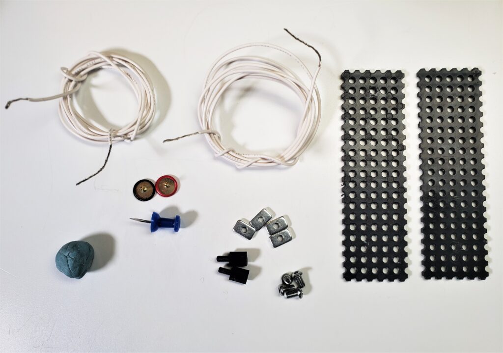
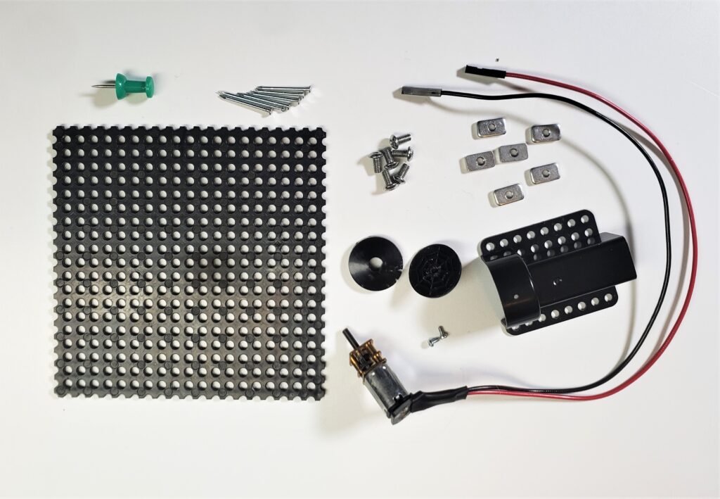
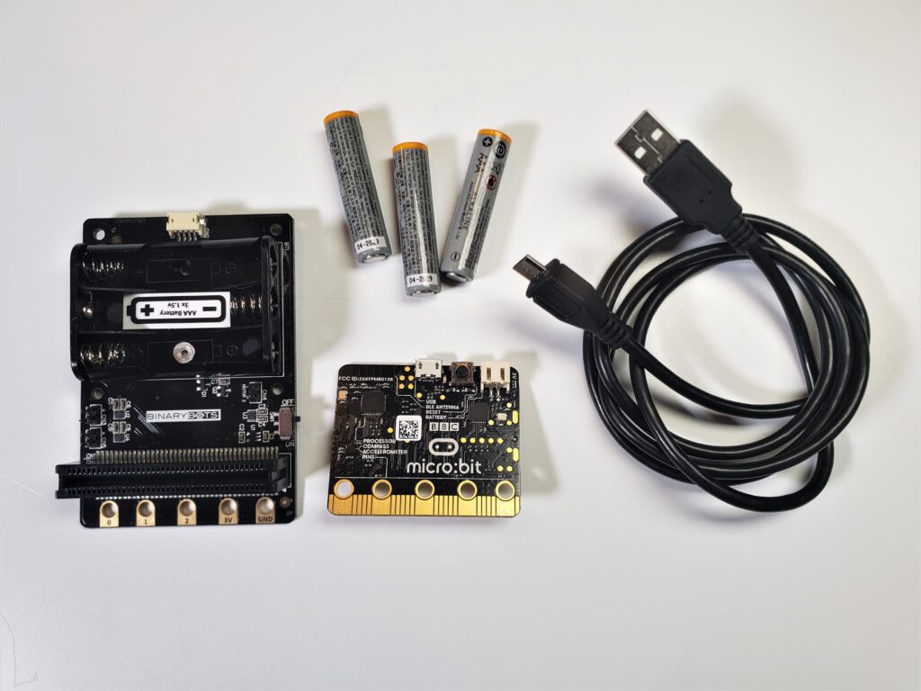
Materials
- micro:bit
- microUSB cable (3ft or more)
- Binary Bots Planet Totem Spider Kit
- If this is your first robotics project, I’d highly recommended to use this kit and follow the tutorial as-is. If you’ve done a few projects before, feel free to make adjustments and modifications. Here are two things to keep in mind:
- This project requires a high torque motor to pull open our door. The motor control system and high torque mini DC motor from this kit were super helpful in building this project.
- The assorted boards, nuts, and bolts were also handy, but could be replaced with similar mechanical parts from another robotics kit or directly from a manufacturer.
- If this is your first robotics project, I’d highly recommended to use this kit and follow the tutorial as-is. If you’ve done a few projects before, feel free to make adjustments and modifications. Here are two things to keep in mind:
- 2 lengths of 24 gauge stranded wire, 3 – 4ft (1 – 1.3m)
- Fishing line, 4′ (1.3m)
- Aluminum, 2″x3″ rectangle (5 – 7cm)
- 8 small nails
- 6 push pins
- Wall sticky putty
Tools
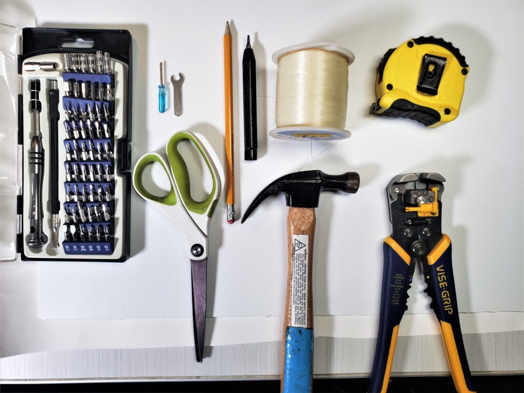
- Driver kit
- Note: the Binary Bots kit does come with an M3 driver (and it’s magnetic, wooo!!!) and a tiny screwdriver.
- Hammer
- Wire Strippers
- Hot Glue Dispenser (not pictured)
- Scissors
- Measuring Tape
- Pencil
Prep and Aluminum Latch Cover
1. Measure and record the width of your door (the inside part).
2. At a 45 deg angle, measure the distance from the door latch to the wall perpendicular to the door hinges.
Note: your particular room setup is likely different than mine. The key thing to keep in mind is that torque is the lowest when it is applied perpendicular. In other words, try to attach the motor as close to perpendicular as possible. A 45 deg angle is likely the smallest angle you’ll want, larger angles will be easier for the motor to pull open the door.
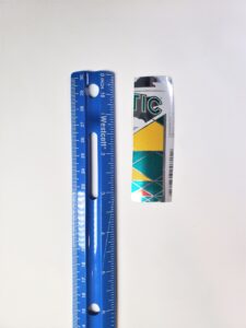
3. Cut a 2″x3″ piece of aluminum (e.g. from a recycled can).
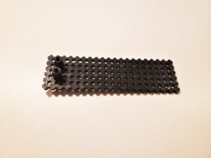
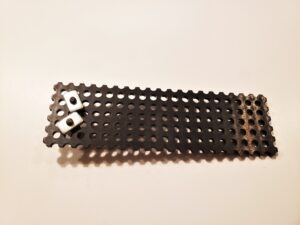
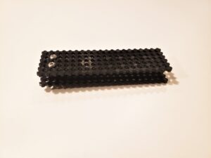
Build it: Door Connection Mechanism!
Materials
To build this part, you’ll need the following pieces from the Binary Bots Kit:
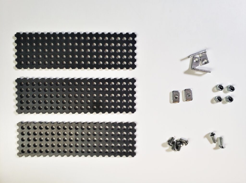
- 3 100x30cm boards
- 2 2-hole 90deg brackets
- 4 6mm M3 bolts
- 4 lock nuts
- 2 8mm M3 bolts
- 2 M3 nuts
Procedure
1. Grab one of the boards. From the left edge, measure and mark the width of the door.
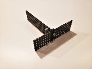
2. Grab a second board. Connect the second board to the first perpendicularly to each other, so that the second board is just to the right of the door width line.
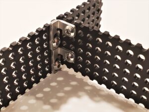
To do this, use both brackets, 4 6mm M3 bolts, and 4 lock nuts.
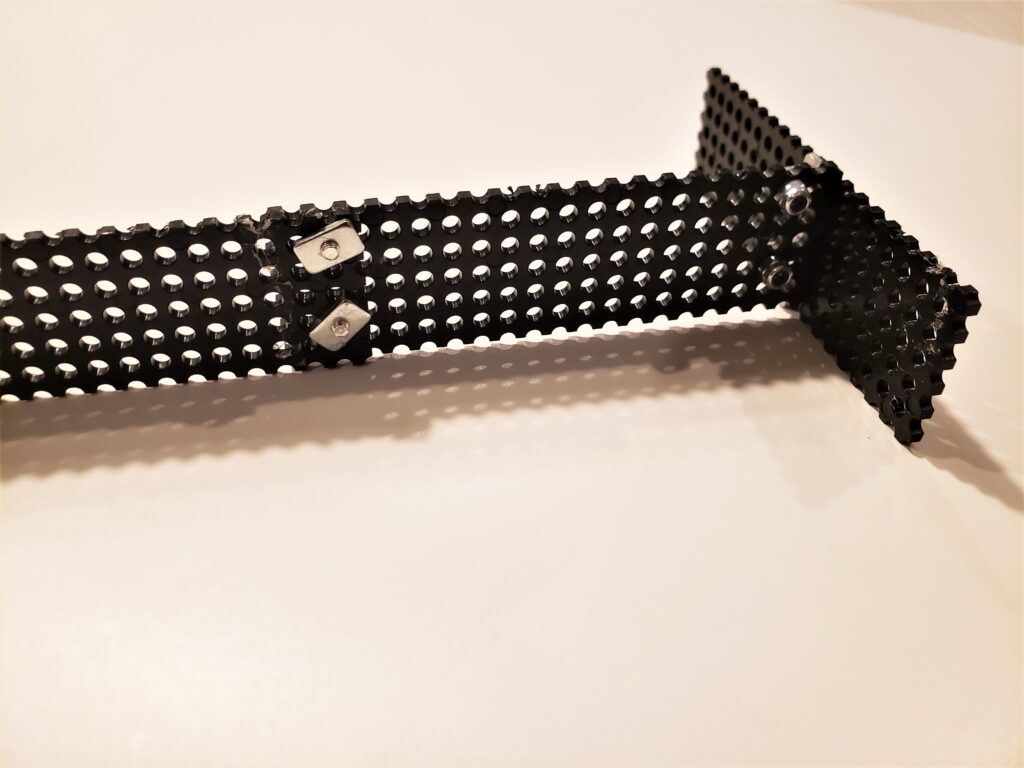
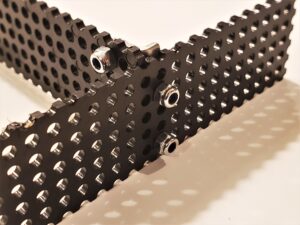
3. Grab the third board and connect it to the second in a straight line using the longer (8mm) M3 bolts and rectangular M3 nuts.
Set aside and move on to the next part, woo!
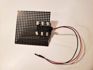
Build it: Pet-Friendly Switch!
Materials
To build this part, you’ll need the following pieces from the Binary Bots Kit:
- 2 100x30cm boards
- 4 6mm M3 bolts
- 4 M3 nuts
- 2 8mm nylon standoffs
You’ll also need:
- 2 3-4ft (1-1.3m) of stranded 24 gauge wire
- Remove about 1in (2.5cm) of the insulation from both ends
- 3 push pins
Procedure
1. Grab one of your boards and attach the nylon standoffs to the left side using two (2) M3 nuts.
2. Grab the second board and use two (2) M3 bolts to secure the second board to the first via the nylon standoffs.
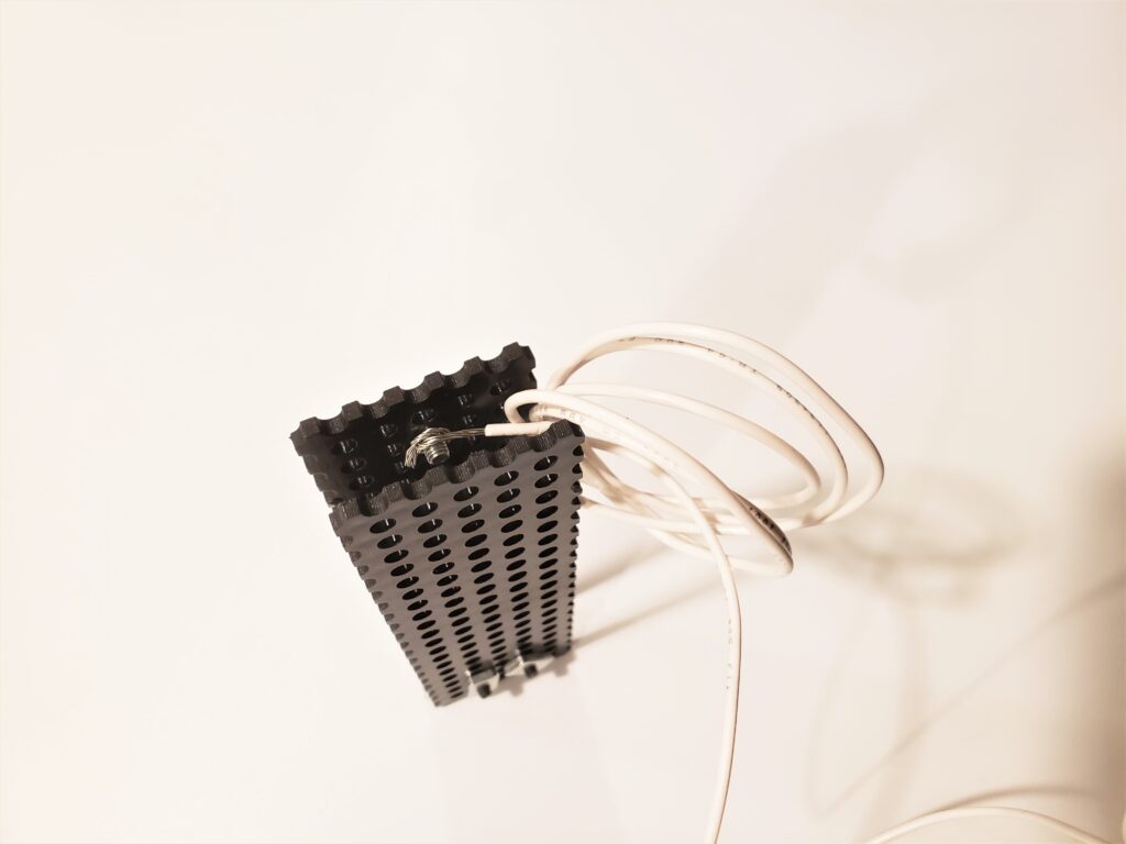
3. Grab one of the M3 bolts and push it through a hole on the far right end of the top board. Wrap one end of the wire around the base of the bolt.
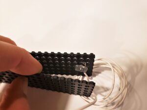
4. Use an M3 nut to secure the bolt in place.
5. Repeat steps 3 and 4 for the bottom board, making sure that the second bolt is directly below the first.
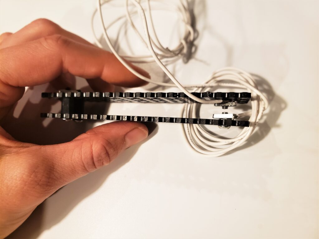
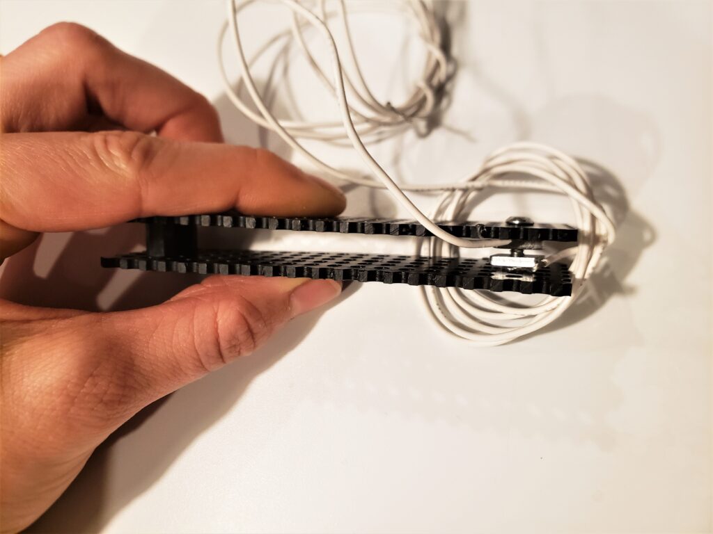
When you close the switch (aka push the boards together), the top and bottom bolts should press together and make full contact.
Build it: Motor Mount!
Materials
To build this part, you’ll need the following pieces from the Binary Bots Kit:
- 1 100×100 cm board
- 1 Tiny Motor with 2 tiny screws (so cute and yet so powerful!)
- 1 Motor Mount (“web launcher”)
- 1 reel set (“web reel”)
- 6 6mm M3 bolts
- 6 M3 nuts
You’ll also need:
- 6 small nails
- 1 pushpin
- 4ft (1.3m) of fishing line (or equally strong line)
Procedure
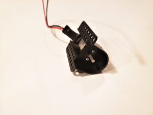
1. Insert and secure the motor into the motor mount with the two tiny screws (highly recommended to use a larger screwdriver if you have one..)
2. Grab the 100x100cm board and use the 6 M3 bolts and nuts to attach the motor on the left side in (roughly) the middle.
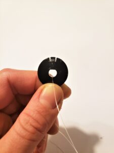
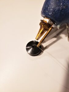
3. Grab the reel and fishing line. Thread one end of the fishing line through the middle of the reel, then wrap around the teeth. Secure with a dab of hot glue.
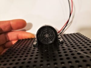
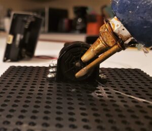
4. Push the two reel pieces together (pinching the thread between the two pieces), and insert into the motor drive shaft so that the web part faces outward. Secure with a dab of hot glue on the outside.
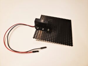
Connect it: Electronics!
Materials
- micro:bit
- microUSB cable
- Binary Bots motor driver board
- 3 AAA batteries
Procedure
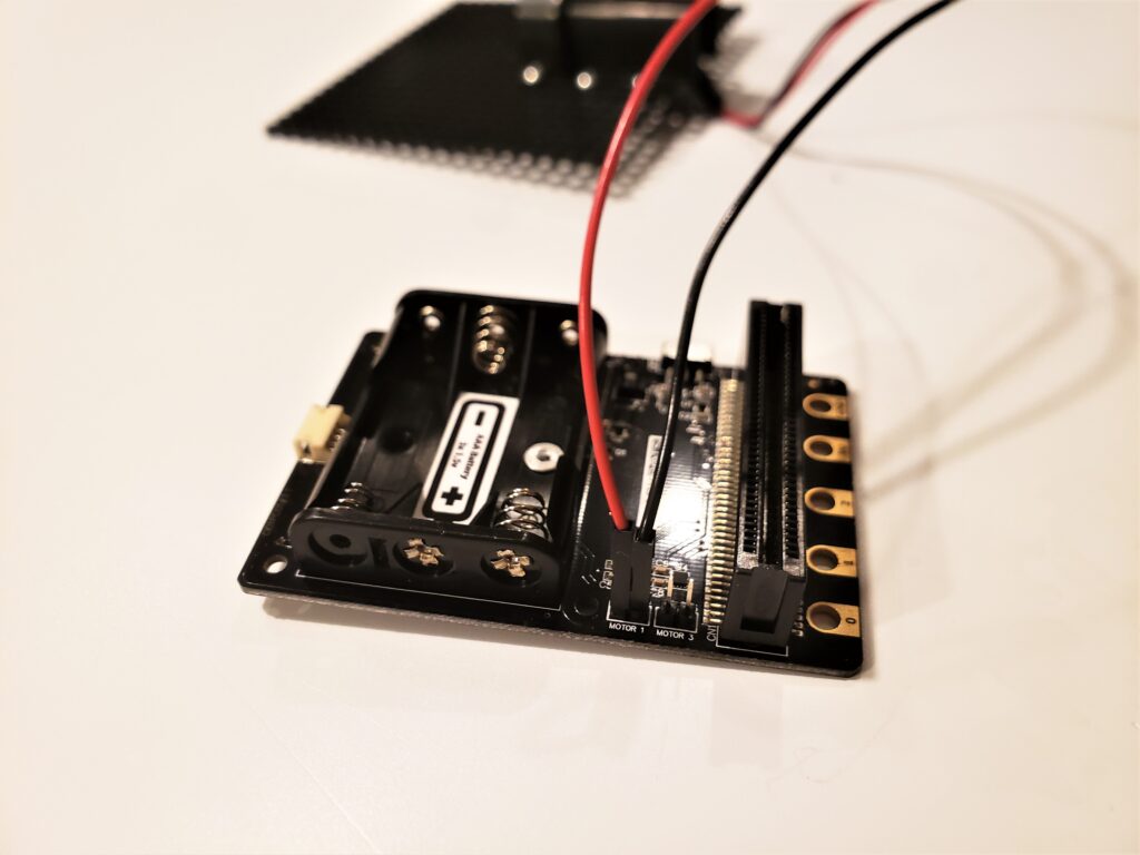
1. Grab the Motor Mount setup you just put together, and plug in the motor to the motor driver board.
Connect the red motor wire to the left header pin labeled “Motor1”. Connect the black motor wire to the right header pin labeled “Motor1”.
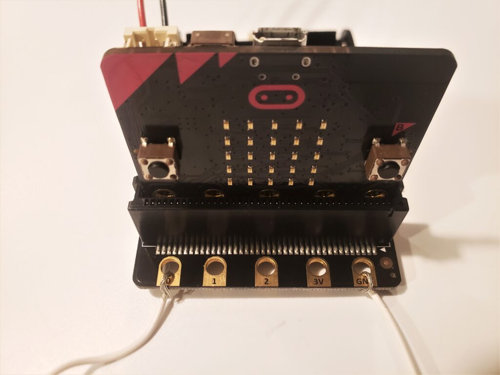
2. Connect the pet-friendly switch! Connect one of the switch wires to the micro:bit P0 pin, and the other to the micro:bit GND pin (doesn’t matter which switch wire goes where).
3. Insert the micro:bit into the motor driver board so that the pushbuttons are facing outwards (away from the motor driver).
4. Insert the batteries into the motor driver board. Locate the power switch and move to “off”.
Code it: Motor Control!
Navigate to the Make Code website: www.MakeCode.org and select the micro:bit option, then “New Project”. It is recommended to rename your project to help you identify what it is doing, like “DogDoorOpener”.
Some background info:
When Pin P0 is triggered (via the switch closing), we want to turn the motor so that it pulls open the door by spooling (aka reeling in) the fishing line. We also want to unspool the fishing line so we can shut the door again. It is also helpful to have a manual way to spool and unspool the motor, as well as to cut power to the motor.. just in case!
Since we are dealing with a DC motor, when we give power to one of the motor leads and ground the other, the motor will rotate in one direction. When we switch power to the motor leads, the motor will rotate in the other direction. Cutting power to both motor leads turns off the motor.
Let’s get started!
First Code Function: Motor Triggered by Doggo Switch
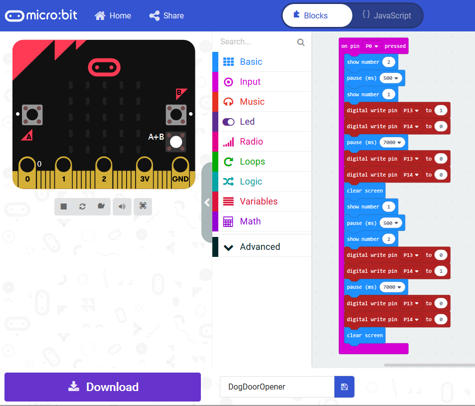
1. Pull out a “when pin is pressed” (input blocks) and make sure it is set to pin P0.
2. Inside the pin P0 block, use the digital write blocks to turn on micro:bit pin P13 (set to 1) and turn off micro:bit pin P14. This turns the motor on in one direction.
The digital write blocks are found under Advanced –> Pins. Select the appropriate pins by clicking on the down arrow.
3. Add a pause for about 7s (7000 ms), then turn the motor off by setting P13 and P14 to 0.
Note: 7 seconds worked well for my setup and my doggo’s needs, but definitely check that this is enough (slash not too much) time to adequately open your door for your needs.
4. Unspool the motor (aka rotate it in the reverse direction) by using a digital write block to turn on P14 and turn off P13. Be sure to unspool the same amount of time as you spool.
5. Optional: use the LEDs to include a countdown/count-up timer to let you know when the motor will be turned on. Also recommended to add a pause between when the switch is pressed as well as when before the motor unspools.
Second Code Function: Manual Open
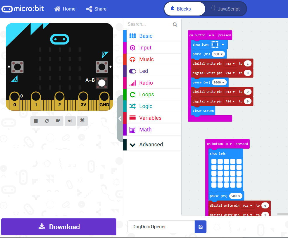
1. To make a manual switch, drag out a “On Button A pressed” (input blocks).
2. Inside this block, use the digital write blocks to turn on micro:bit pin P13 (set to 1), and turn off micro:bit pin P14 (set to 0).
3. Add a pause block for ~3s (3000 ms).
4. Turn off the motor! (by setting the digital write blocks to 0)
5. Optional: Show an icon before you turn the motor on so you know which way the motor will be turning.
For mine, I chose a rectangle outline so indicate “open door”, choose something that makes sense to you and your brain.
Third Code Function: Manual Close
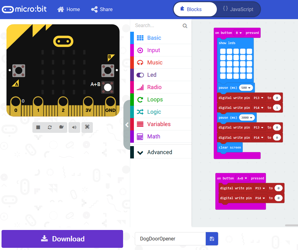
1. To make a manual switch, drag out a “On Button B pressed” (input blocks).
2. Inside this block, use the digital write blocks to turn on micro:bit pin P13 (set to 0), and turn off micro:bit pin P14 (set to 1).
3. Add a pause block for ~3s (3000 ms).
4. Turn off the motor! (by setting both digital write blocks to 0)
5. Optional: Show an icon before you turn the motor on so you know which way the motor will be turning.
Fourth Code Function: Turn Off Motor
1. Pull out a “On Button A+B pressed” block.
2. Use two digital write blocks to set both P13 and P14 to 0.
Install it!
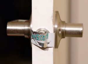
1. Use some of the wall sticky putty to wrap the aluminum around the door latch.
Bend the aluminum around the latch so that the door is able to fully close, but prevents it from sticking.
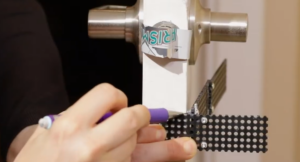
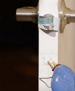
2. Using your hot glue dispenser, glue the short end of the door mechanism piece to the door width, just below the latch. Glue the longer piece to the door to provide extra stability.
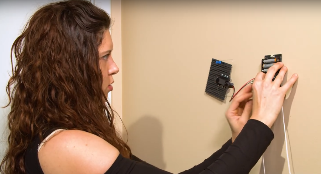
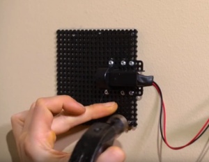
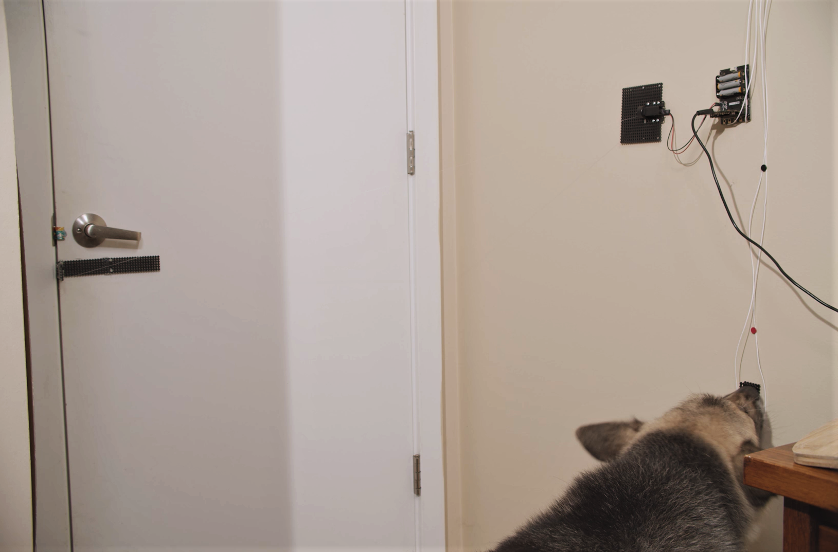
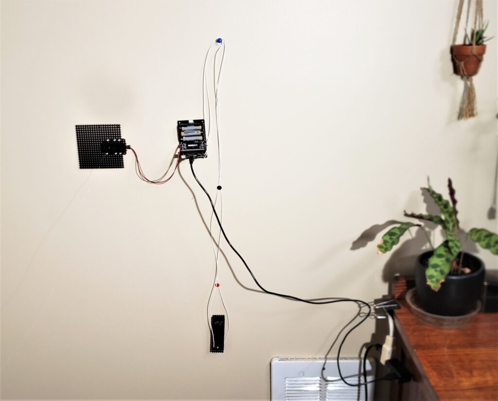
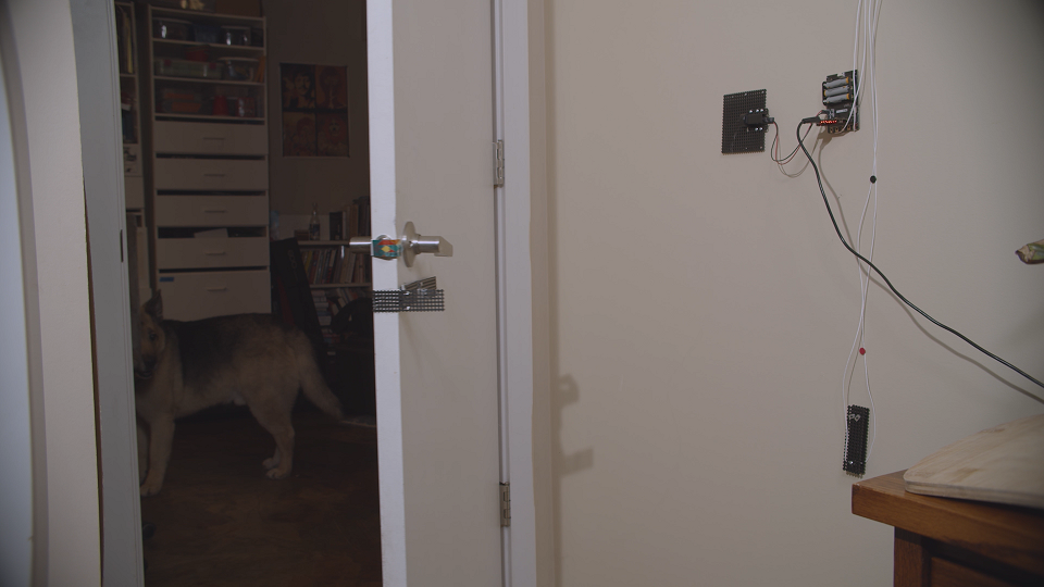
3. Attach the motor mount and the motor controller board to the wall. Use the push pins temporarily to hold the pieces in place, then use 6 nails to secure the motor controller, and 2 to secure the motor controller board.
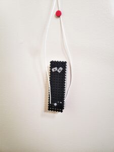
4. Use the wall sticky putty to attach the switch in a place that is convenient for whoever will be triggering the door to open. Since my dog is fairly large, I installed it about 1.5ft (0.5m) up from the floor so that doggo could press the switch with his nose.
I preferred to sticky putty so I could adjust the switch and remove things as necessary, but if you want to make this permanent you can use nails or hot glue.
5. Use the pushpins to secure the switch wires to the wall and prevent them from getting disconnected.
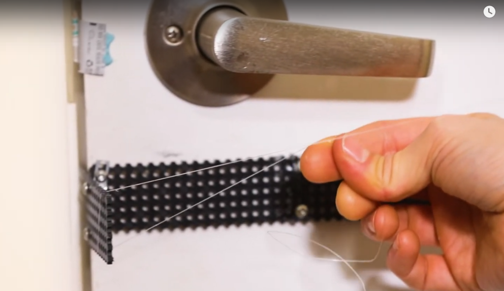
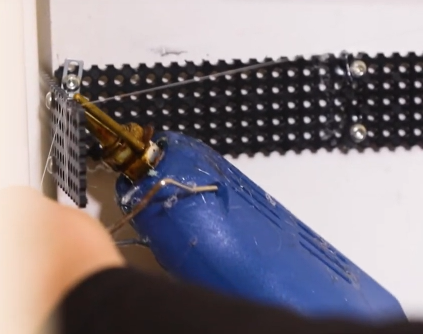
6. Attach the fishing line between the motor reel and the door mechanism. Close the door fully, then wrap the fishing line around the door mechanism a few times so that it is taught, then secure with hot glue.
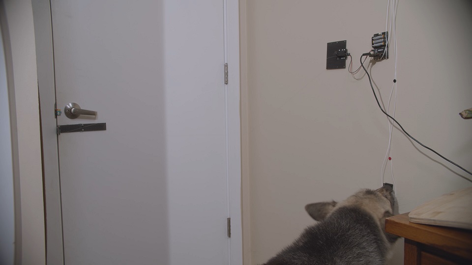
Test & Deploy! And make your home more accessible, hooray!
Huzzah!! Ready for the testing phase! Power up the micro:bit (via the microUSB cable) and turn on the motor controller board.
Trigger the switch and check that the motor pulls open the door enough for your furry friend to escape! And also that the motor unspools so you can close the door again.
Very likely something will need to be adjusted/fixed, so check all of the buttons, make sure the system is secure to the wall and does not block anything.
Once you’ve tested your Doggo Door Opener, show it to your pet! … And maybe train them, ha. I did this by using treats on top of the switch, so that my dog accidentally triggered the switch, then he saw that door opened. It took a few tries (I also ended up giving it a command of “get the switch”), but eventually he figured it out! And now I can leave my lovely but oh-so-anxious dog home alone without worrying he will trap himself (on purpose? I have no idea).
Hooray for using tech to make our own lives and the lives of others easier and better!
Let me know if you have any questions, run into any issues, or have other ideas for this project, I’d lovelovelove to see what you make so please share your creations!
Happy making, friends!
3 thoughts on “micro:bit Dog Door Opener”
Comments are closed.