Build a portable gas monitor to check for dangerous levels of hazardous gases in your home, community, or on the go and prevent your friends from lighting a cigarette during a gasoline fight.*
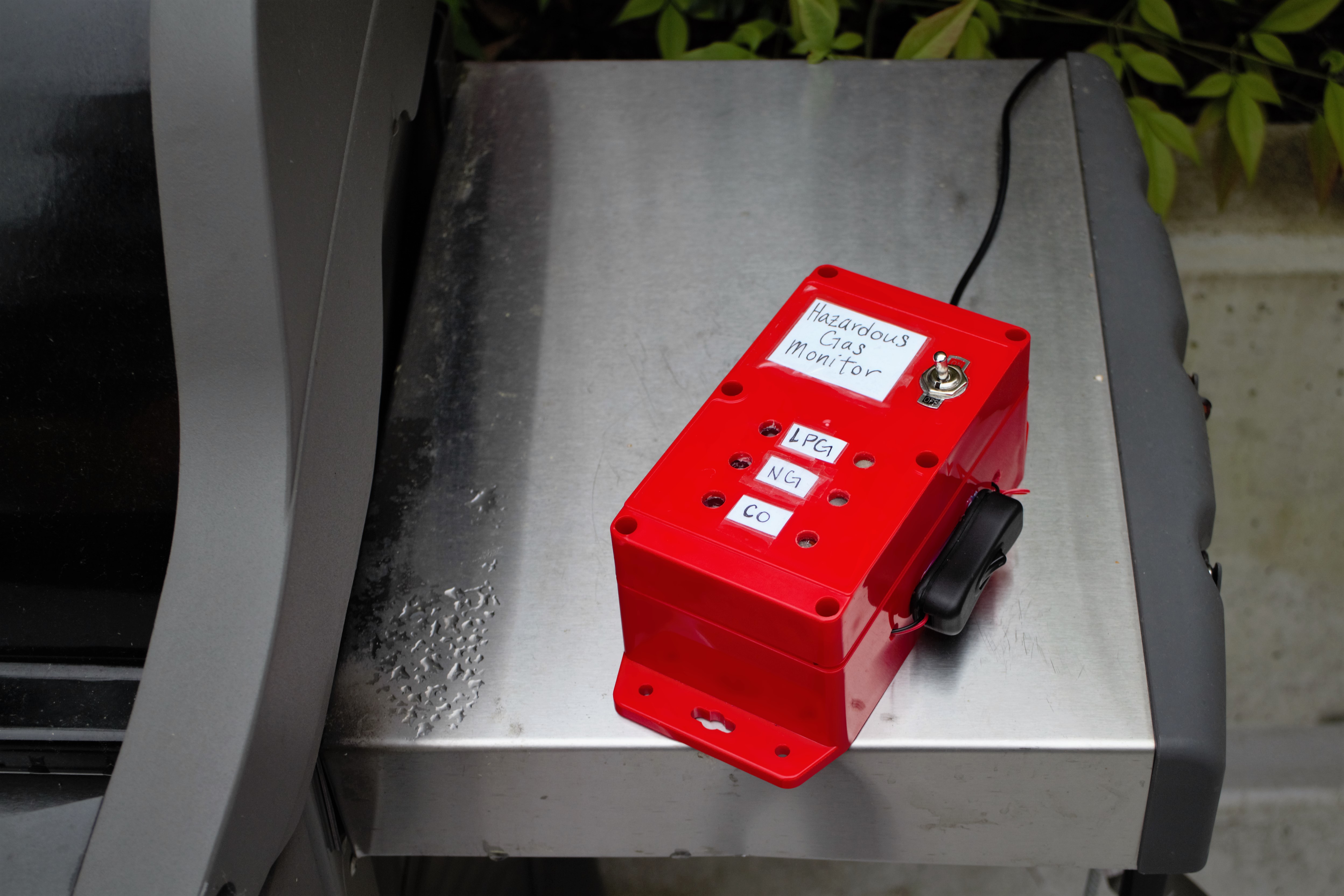
This tutorial shows you how to build a web-connected “canary” monitor for three hazardous gases: Liquid Propane Gas (“LPG”), Methane (aka natural gas), and Carbon Monoxide (“CO”) . Using the Particle Photon microcontroller, the sensor readings are converted into parts-per-million (“PPM”) and uploaded to the data.sparkfun.com web service.
*Please note that this is solely a movie reference — gasoline fights should probably be avoided in real life.
Helpful Background Info!
1. How to set up the Particle Photon.
2. Pushing data to the data.sparkfun.com web server.
3. New to relays? Check out this a handy reference.
4. Here’s a helpful overview on the N-Channel MOSFET.
5. For powering the Photon, here’s a thorough guide on the Photon Battery Shield.
6. Highly recommended to peruse the datasheets for the three gas sensors.
Choosing a Battery!

The gas sensors used in this project require a fair amount of current, about 0.17 A each at 5V. To make the system portable, we’ll need a high capacity battery. One easy, and affordable, option is to use four (rechargeable) AA batteries in series. These batteries will last about 4 hours.
Another option is to use a lithium ion battery (“LIB”). LIBs have a higher capacity than AAs, but typically run at a lower voltage. If you go with this option, you may need to include a correction factor when you calculate the sensor value or boost the battery voltage with a transistor or other component.
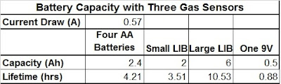
The photo above shows a table with the approximate lifetime of a few different battery options.
If all of this sounds confusing, here’s a more thorough tutorial.
Materials!

Here’s a Wish List that includes all the necessary components for this project!
Microcontroller and Accessory Components
– Particle Photon microcontroller
– SparkFun Photon Battery Shield
– One 2000 mAh Polymer Lithium Ion Battery
– Surface Mount DC Barrel Jack
– Barrel jack to USB power supply cable
– Optional: Male-to-Female JST connector cable
Gas Sensor Circuit
– One (1) 4 AA battery case
– Four (4) AA Rechargeable Batteries
– One (1) Toggle Switch (SPST switch)
– Three (3) 10 kΩ resistors
– Optional: Electrical connectors (3-5)
LPG (MQ6) Gas Sensor
– One (1) 4.7 kΩ resistor
– One (1) 5V Voltage Regulator
Methane (MQ4) Gas Sensor
– One (1) 4.7 kΩ resistor
– One (1) 5V Voltage Regulator
Carbon Monoxide (MQ7) Gas Sensor
– One (1) 4.7 kΩ resistor
– One (1) 5V Voltage Regulator
– One (1) 5V SPDT Relay
– One (1) N-Channel MOSFET
– One (1) 10 kΩ potentiometer
– One (1) 10 kΩ resistor
Tools!
– Soldering Iron
– Wire cutters/strippers
– Drill
– Screwdriver
– Epoxy (or hot glue)
Build it! Electronics


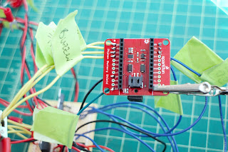
1. Solder gas sensor breakout boards to gas sensors. Orientation doesn’t matter, just be sure that the silkscreen (aka labels) are facing down so that you can read them (had to learn that one the hard way..). Solder wires to the gas sensor breakout board.

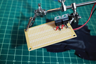
2. Solder three voltage regulators to the PCB board. For each regulator, connect positive battery output to the regulator input, and connect middle voltage regulator pin to ground.
3. Connect the LPG (MQ6) and Methane (MQ4) sensors.
For each sensor:
- Connect H1 and A1 to the output of one of the voltage regulators (recommended to use an electrical connector).
- Connect GND to ground.
- Connect B1 to Photon analog pin (LPG goes to A0, Methane to A1)
- Connect a 4.7 kΩ resistor from B1 to ground.
4. Connect the CO (MQ7) gas sensor.

*Aside: The MQ7 sensor requires cycling the heater voltage (H1) between 1.5V (for 90s) and 5V (for 60s). One way to do this is to use a relay triggered by the Photon (with the aid of a MOSFET and potentiometer) — when the relay is not powered, the voltage across H1 is 5V, and when the relay is powered the voltage across H1 is ~ 1.5V.
- Connect GND to ground.
- Connect B1 to Photon analog pin (A2). Connect 4.7 kΩ resistor from B1 to ground.
- Connect A1 to third voltage regulator output (5V source).
- Connect Photon 3.3V pin to positive relay input.
- Connect Photon Digital Pin D7 to left MOSFET pin, and a 10 kΩ resistor to ground.
- Connect middle MOSFET pin to relay ground pin. Connect right MOSFET pin to ground.
- Connect relay Normally Open (“NO”) pin to H1, and the Normally Closed (“NC”) pin to middle potentiometer pin.
- Connect right potentiometer pin to ground, and left pin to H1.
- Adjust potentiometer resistance until it changes the relay output to ~ 1.5V when the relay receives power.

5. Connect an LED and 10 kΩ resistor to each of the Photon digital pins D0, D1, and D2. Connect buzzer to Photon digital pin D4.

6. Connect toggle switch between battery pack and PCB board power. Recommended to include an electrical connector for the battery pack to make it easier to switch out batteries.
7. Connect lamp switch between LIB and Photon battery shield — recommended to use an extra JST cable for this to keep the LIB battery cable in tact (and make it easier to install the lamp switch).
8. Label wires!
Build a Case!

1. Drill hole for toggle switch on case lid.
 2. Drill 3 holes in the case lid for the LED lights to shine through, and 3 holes for the gas sensors to have air contact. Adhere components on the inside of the lid.
3. Drill hole in the side of the case for barrel jack USB cord to connect to the Photon Battery Shield.
4. Drill two small holes on the side of the case for the lamp switch cable. Adhere lamp switch to side of case.
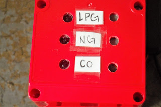
5. Label the LEDs with its corresponding gas sensor on the outside of the case.
6. Check electrical connections and, if everything is good to go, coat electrical connections in epoxy or hot glue.
Calculate Gas Sensor PPM!
Each of the gas sensors outputs an analog value from 0 to 4095. To convert this value into voltage, use the following equation:
Sensor Voltage = AnalogReading * 3.3V / 4095
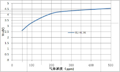
Once you have the sensor voltage, you can convert that into a parts per million (“PPM”) reading using the sensitivity calibration curve on page 5 of the gas sensor datasheets. To do this, recreate the sensitivity curve by picking data points from the graph or using a graphical analysis software like Engauge Digitizer .
Plot PPM on the y-axis and V_RL on the x-axis, where V_RL is the sensor voltage. There is a lot of room for error with this method, but it will give us enough accuracy to identify dangerous levels of hazardous gases. Estimated error bars are around 20 PPM for the LPG and Methane sensors, and about 5 PPM for the CO sensor.
Next, find an approximate equation for the PPM vs. V_RL curve. I used an exponential fit (e.g. y = e^x) and got the following equations:
LPG sensor: PPM = 26.572*e^(1.2894*V_RL)
Methane sensor: PPM = 10.938*e(1.7742*V_RL)
CO sensor: PPM = 3.027*e^(1.0698*V_RL)
Program it!
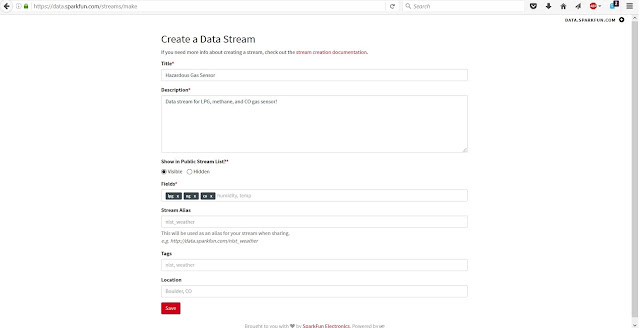
First, set up a data stream on the [data.sparkfun.com service](http://data.sparkfun.com). Next, write a program to read in the analog value of each gas sensor, convert it to PPM, and check it against known safe thresholds. Based on OSHA safety standards, the thresholds for the three gases are as follows:
- LPG: 1,000 PPM
- Methane: 1,000 PPM
- CO: 50 PPM
If you want to get up and running quickly, or are new to programming, feel free to use my code! Use it as-is or modify to suit your particular needs.
Change the following in the code:
1. Copy and paste your data stream public key to the array called `publicKey[]`.
`const char publicKey[] = “INSERT_PUBLIC_KEY_HERE”;`
2.Copy and paste your data stream private key to the array called `privateKey[]`.
const char privateKey[] = “INSERT_PRIVATE_KEY_HERE”;
To monitor the Photon output, use the Particle driver downloaded as described in the [“Connecting Your Device” Photon tutorial](https://docs.particle.io/guide/getting-started/connect/photon/). Once this is installed, in the command prompt, type `particle serial monitor`. This is super helpful for debugging and checking that the Photon is posting data to the web.
Be a Citizen Scientist!

Now we get to test and employ our gas monitor! Turn the batteries for the gas sensors on using the toggle switch, wait about 3 – 5 minutes, then turn the Photon on with the lamp switch (the gas sensor heater coils take some time to heat up). Check that the Photon is connected to WiFi (on-board LED will slowly pulse light blue) and is uploading data to the server. Also check that the gas sensor readings increase when in proximity to hazardous gases — one easy, and safe, way is to hold a lighter and/or a match close to the sensors.
Once up and running, use the sensor to monitor for dangerous gas leaks around your home, school, workplace, neighborhood, etc. You can install the sensor in one location permanently, or use it to check gas levels in different locations (e.g. SoCal..).
Educator Extension!
This project is a perfect excuse for a hands-on chemistry lesson! Use the monitor to learn the fundamentals of various gases — what kinds of gases are in our environment, how are different gases produced, and what makes some of them hazardous or dangerous.
Study the local environment and use a lil’ math to record and plot LPG, Methane, and CO in specific locations over time to see how the levels change. Use the data to help determine what causes changes in the gas levels and where/when gas concentrations are the highest.
More to Explore!

Monitor hazardous gas concentrations around your neighborhood or city and use the results to identify problem areas and improve public safety.
Use Bluetooth, or your smartphone WiFi, to connect to the Photon and upload data to the web wherever you are!
Include other sensors, gaseous or otherwise , to create a more comprehensive environmental monitoring system.