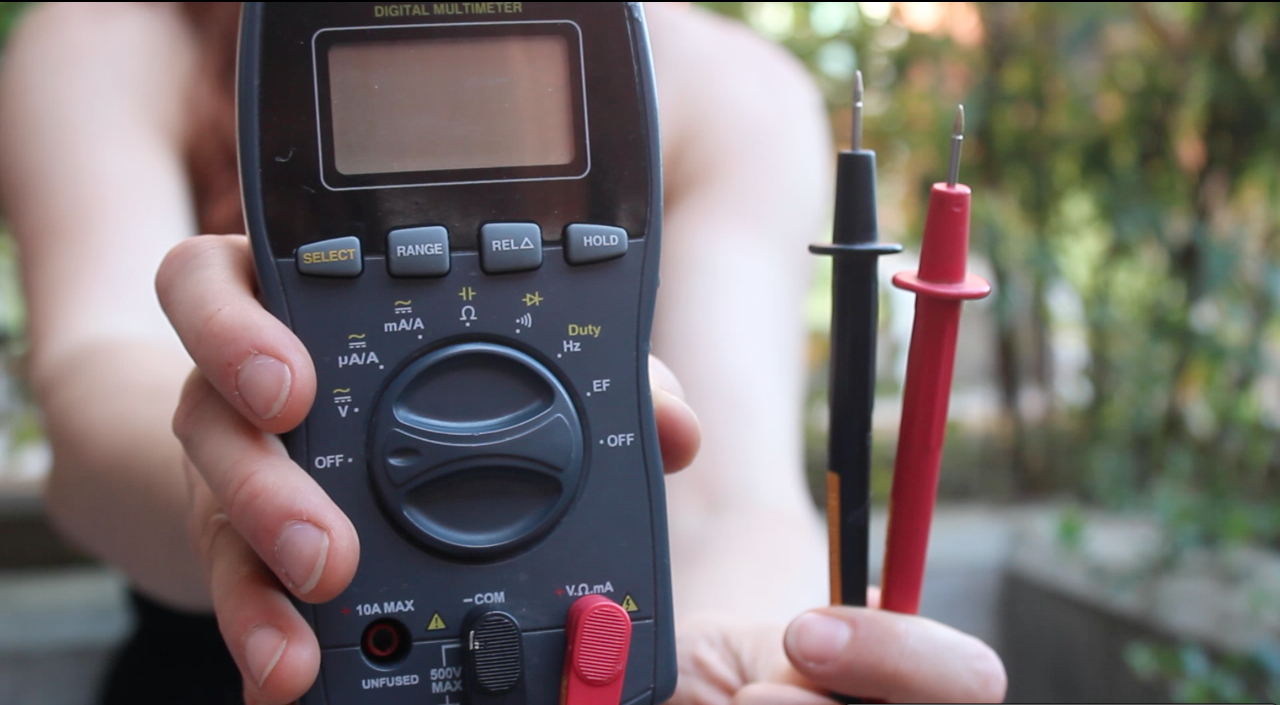
Checking your car battery life, debugging circuits, and finding that pesky short are all super useful functions that can be performed with just one awesome tool: the multimeter!
First of all, what the heck is a multimeter?? Excellent setup question! It’s a handheld device with bunch of different electrical meters — hence, multi-meter!
Measuring voltage, current, resistance, and continuity (aka electrical connection) are the most common uses of a multimeter. Read on to learn what this means, how to do it yourself, and how to choose your very own multimeter!
Choosing a Multimeter!


There are a few key differences between multimeters, the main one being analog versus digital:
Analog multimeters show real-time changes in voltage and current, but can be difficult to read and log data.
Digital Multimeters are easier to read, but may take some time to stabilize.
There are also auto-ranging multimeters, that automatically detect the measurement range, and manual ranging multimeters where you have to choose a range yourself (or start with the highest setting and work down).

Other than those two main differences, you’ll want a multimeter that has separate ports for current and voltage measurements (this is a safety issue, both for the meter and for yourself).
Next comes the fun part: features! Multimeters all have voltage and current meters (otherwise they’d just be called voltmeters and ammeters!), and most can also measure resistance. There are a variety of other “extra” features depending on manufacturer and cost (e.g. continuity, capacitance, frequency, etc.).

Second-to-lastly, there are a ton of different types of probe leads, including alligator clips, IC hooks, and test probes. Can’t decide? Here’s a kit that has four different types!
Lastly, always check the multimeter maximum voltage and current ratings to be sure that it can handle what you want to use it for.
Using a Multimeter!
But first! A quick overview of voltage, current and resistance!
My favorite analogy for electricity is the “water flowing through a pipe” analogy. In this analogy, voltage is similar to the water pressure, current is like the water flow (except with current you have electrons instead of water molecules!), and resistance is akin to the size of the pipe. Check out this tutorial for an awesome and thorough overview of electricity.
Keeping these analogies in mind helps us to figure out how, and what, we are measuring.
 Measuring Voltage:
A voltage measurement tells us the electrical potential, or pressure, across a particular component.
Voltage is basically the “oomph” in our circuit, s so we want to avoid drawing any power from the circuit when we take a voltage measurement. This means we need to measure voltage in parallel with a particular component using infinite (or really, really high) resistance to prevent any electrical current from flowing into the meter.
Using a multimeter to measure voltage across a component (or battery!):

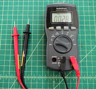
1. The black multimeter probe goes into the COM port, and the red probe into the port marked with a “V”.
2. Switch the dial to the “voltage” setting (choose the highest setting if you have a manual ranging multimeter).
3. Place black probe on negative side of the component, and red probe on positive side (across, or in parallel with the component). If you get a negative reading, switch the leads (or just note the magnitude of the voltage reading).
Read the meter output and you’re done! Not too bad 🙂
Measuring Current:

Taking a current measurement tells us the amount of electricity flowing through a given component or part of a circuit.
To measure current, we need to measure all of the flow in our circuit without consuming any power from the circuit and reducing the current measurement. This means we measure current in series with a component and we want our meter to have zero resistance.
Using a multimeter to measure current through a component:
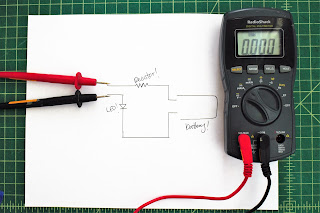 1. The black multimeter probe goes into the COM port, and the red probe into the port marked with an “I” or an “A” (or “Amp”).
2. Switch dial to the current setting (choose highest setting if you have a manual ranging multimeter).
3. Connect red probe to current source, and black probe to the input of the component, so that the current flows from the source, through the meter, to the component (in series with the component).
Read the meter output! If you’re not getting a reading, switch to a lower setting.
Measuring Resistance:
Measuring resistance is pretty straightforward, but you do have to disconnect individual components from a circuit to get their actual resistance, otherwise the rest of the components in the circuit can interfere with your measurement.
Using the multimeter to measure resistance of a component:
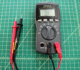
 1. Put the black probe in COM port, and red probe in the port marked with a “Ω” or “Ohm” — it should be the same port as the voltage port.
2. Switch dial to setting marked with a “Ω” (may have to choose approximate range for manual ranging multimeter).
3. Place probes on either side of the component (orientation doesn’t matter).
Read the meter output and you have conquered resistance!
Bonus: Measure Continuity!
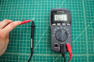
The continuity measurement checks if two points in a circuit are electrically connected, otherwise known as a conductance test. Before measuring continuity, be sure that the circuit power is OFF.
Using the multimeter to measure continuity:

1. Place black probe in COM port, and red probe in voltage port.
2. Switch dial to setting marked with an audio symbol.
3. Place probes at points you want to check — if the meter makes a beep sound, it means the two points are connected.
Le fin!
Go forth and measure all the things!

Now that we know how to use a multimeter, get crackin’ on all those at home, DIY projects! To get you started, here are a few quick, practical, & fun projects:
1. Measure the resistance of your skin! Change the distance of the probe leads and see how resistance changes. Lick your fingers (or dip them in water) to see how moisture affects resistance!
2. Measure the voltage across AA, 9V, or other batteries around the house/workplace/school to locate dead, or dying, ones.
3. Make a lemon battery and measure the voltage and current output.
4. Use the continuity setting to check if different materials conduct electricity.
Looking for more info on multimeters?
Check out this in-depth guide by the folks at Tools Critic!

Hello jenfoxbot, I wanna buy a multimeter but didn’t get the different differences between multimeters. Thanks
Hi Richard! Thanks for the comment — apologies for the delay, looks like it got flagged as spam for some weird reason. Anyway, there are two types of multimeters: digital and analog. I’d recommend a digital multimeter. From there, a higher price will get you a larger measurement range and better safety protection. If you’re using one for hobbyist purposes at low voltages, you can pick one up at your local hardware store. Read through the specs and decide what’s best for your needs. Hope that helps!
Hello jenfoxbot,
Thank you for your valuable post. I just got basic about digital and analog multimeter.
What is your personal recommendation that I can buy?
Glad the tutorial was helpful!
Re: multimeter, it really depends on what you need it for– here’s a great general purpose hobbyist multimeter that doesn’t break the bank, and this one is a level up in quality but also a bit more expensive. If you need more serious applications (see: electrician), here’s an excellent, industry-standard multimeter.