Used by hobbyists and professional engineers alike, breadboards allow us to quickly build all sorts of circuits!
Breadboards got their name because in a time long ago, engineers used to use wooden cutting boards! They would hammer in nails and wrap wires to make connections. Not only was it tedious, but the cooks got frustrated that their breadboards kept getting stolen and used for definitely-non-food-purposes, so eventually someone invented the plastic breadboard to keep kitchen utensils safe. Hooray!
Similar to wires, plastic breadboards use conductive metal and insulating plastic to create paths where electricity can flow (the metal parts), and breaks where it cannot flow (the plastic parts).
If we were to look underneath a breadboard and peel off the backing, we would see something like this:
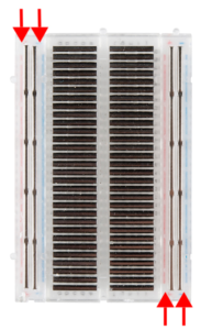
What do you notice?
The middle of the breadboard is different than the outsides. On outside of the breadboard, on both the left and the right sides, there are two long strips of metal. These are called “Power Rails”, or “Power Buses”, and one of the strips by itself is called a “Power Bus.”
Flipping the breadboard back over, the top, where we make our circuit connections, looks like this:
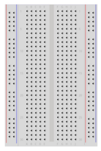
Looking at our Power Buses, there are colored lines next to them. While these are just guidelines (ahhhh sorry for the terrible pun, lol), the colored lines are super helpful for keeping track of how we connect our battery or power supply to the breadboard. Typically blue means negative, or ground (“gnd”), and red means positive.
The middle gap of the breadboard is called the trench. This separates the two identical middle halves of the breadboard. The trench is sized so that components with more than 3 pins can fit across.
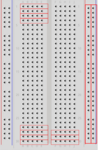
The rows of the breadboard are marked with numbers, in this case numbers 1 – 30. The columns are marked with letters A, B, C, D, and E. Each row has a set of 5 holes that are connected by the piece of metal we saw on the bottom, as well as metal pins on the inside that hold wires and component pins in place. Some of the hole groups that are electrically connected are shown on the photo above with red rectangles.
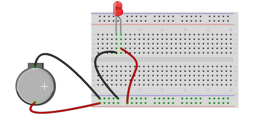
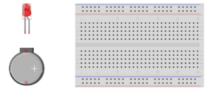
Now let’s make some circuits! We’ll need four (male-to-male) jumper wires and the following parts:
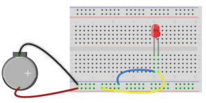
Next, we’ll connect the battery to the power rails. If your battery case does not plug directly into the breadboard, grab two jumper wires for this.
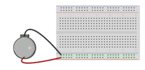
The battery case that you are using might change how you connect your battery to the circuit, and that’s okay! The important part is that you connect the positive side of teh battery to one power bus, and the negative side of the battery to the other. Be sure that both sides of the battery are in different power buses (if you feel the battery getting warm it may indicate that it is short-circuited, this would be the place to double check).
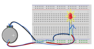
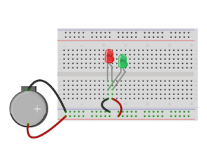
Next, let’s connect our light! Grab your remaining jumper wires and your LED.
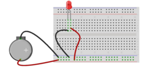
Insert the LED legs so that both legs are in two different rows (reminder: rows are marked with numbers). Connect the positive side of the battery to the longer LED leg. Connect the negative side of the battery to the shorter LED leg.
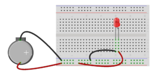
Voila! If the LED is connected to the battery in a circuit, it will light up!
Try moving your LED to a different part of the breadboard. Observe what happens!
Does wire color matter? Try two different colored wires and see what happens!
Finally, let’s end our exploration by tracing the path of the electricity.
Electric current is defined to flow from positive to negative. That means our electric current, which is made up of moving charges, flows out of the positive side of the battery, through the wire and into the breadboard power bus. It flows through the power bus, then up and out the red wire to the breadboard row where it can travel up the LED where it does work (and loses some energy) to make the LED turn on.
Then the (less energetic) electric current flows out of the LED through the shorter leg, into the breadboard row where it flows into the black wire. It then flows out of the black wire and into the second power bus, through the power bus and back to the negative side of the battery.
Our circuit is a circle! The moving charges that leave their home must also come back, but they come back more tired and into the back-door (which is to say, the negative side!).
Other helpful terms:
- Current: The amount of charge flowing past a point in our circuit.
- Current units are given in Amperes/Amps, or A
- Voltage: The potential energy, or pushing force, across a component in our circuit. A higher voltage means more pushing force.
- Voltage units are given in Volts, or V.
- Resistance: How much a particular component resists the flow of electricity.
- Resistance units are given in Ohms, or O
- Capacitance: How much current a battery can provide over time.
- Capacitance units are given in Amp-hours, or Ah.
There are two ways to connect components:
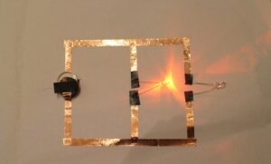
1. In series: connect components in line with one another, or head-to-tail.
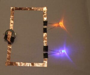
2. In parallel: connect components in loops, or head-to-head.
Going Further!
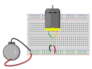
You are now ready to tackle more circuits! Try adding more lights, or using different components. What happens when you add different kinds of components together? How many ways can you combine multiple components ?What sorts of projects could you use these circuits for? Share your creations with us, we always love to see and share!
And of course, please let us know if you have any questions, we are here to help!
Other useful tutorials:
Happy making!
One thought on “How to use a Breadboard!”
Comments are closed.